Home – Our Services – Shell and Tube Heat Exchangers
Shell and Tube Heat Exchangers
Shell and tube heat exchanger solutions tailored to your processes
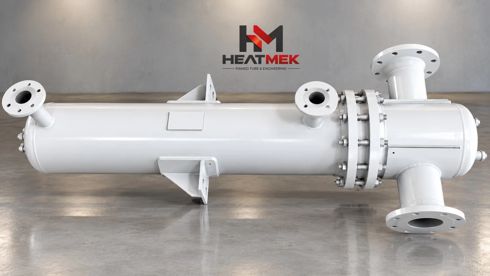
Shell and Tube Heat Exchangers: A Powerful Core for Industrial Heat Transfer
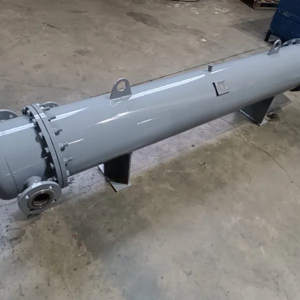
A shell and tube heat exchanger is critical industrial equipment that transfers heat over a large surface between two fluids at different temperatures without allowing them to mix. Heatmek designs shell and tube exchangers for demanding pressures, including 350 bar on the shell side and 1400 bar on the tube side, and extreme temperatures from 200°C to 600°C. They provide durable, thermal-shock-resistant solutions across applications from oil refineries to food factories.
The basic principle is that one fluid flows inside the tubes, on the tube side, while the other flows through the surrounding shell, on the shell side. Grooved tubes or turbulator-equipped tubes are used to enhance heat transfer.
Our Shell and Tube Heat Exchanger Types
Shell and Tube Heat Exchangers
Shell and Tube Condensers
Shell and Tube Evaporators
Fixed Tubesheet and U-Tube Designs
Structure and Main Components of a Shell and Tube Heat Exchanger
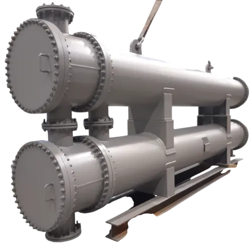
Heatmek shell and tube heat exchangers are manufactured in accordance with international standards, including TEMA, ASME and EN 13445, and comprise the following main sections:
- Front Head: Directs the fluid entering the tube side.
- Shell: The cylindrical structure surrounding the tube bundle, through which the shell-side fluid circulates. Expansion joints are located in this section.
- Rear Head: The section where the fluid completes or reverses its tube-side flow.
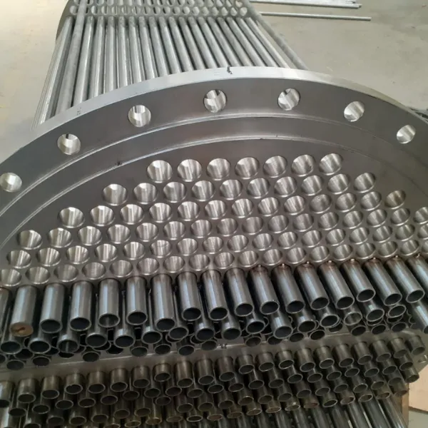
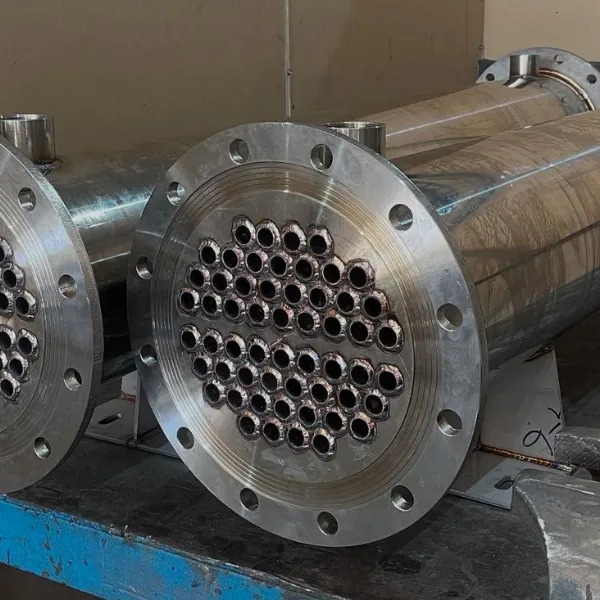
- Tube Bundle and Tubesheets: Perforated plates secure the tubes and prevent the fluids from mixing. Tubes are generally arranged in triangular or square patterns with a pitch of 1.25 times the tube diameter.
Design Types: U-Tube and Straight-Tube Heat Exchangers
Heatmek offers two main designs according to the physical and thermodynamic requirements of the process:
- U-Tube Heat Exchangers: U-shaped tubes accommodate expansion caused by large temperature differences within their own structure. They are preferred for high-capacity applications and systems benefiting from the pressure resistance of circular sections.
- Straight-Tube Heat Exchangers: Straight tubes are secured through tubesheet connections. Their main advantage is easy mechanical cleaning of the tube interiors. They provide high performance up to 350°C in food and chemical applications where hygiene is critical.
Material Selection and Manufacturing Technology
For shell and tube heat exchanger manufacturing, our specialists select materials according to the fluid’s corrosiveness and temperature. Tube materials can include copper, stainless steel, carbon steel, seamless or welded, nickel silver, brass and titanium. Shell materials range from carbon steel to duplex stainless steels.
Baffle design is critical in manufacturing. Baffles force the shell-side fluid to follow a zigzag path around the tube bundle, increasing turbulence and the heat transfer coefficient.
Applications and Industries
Their flexible design and durability make these exchangers suitable for almost every industry:
- Oil and Refining: Crude oil heating, gas liquefaction and heavy oil cooling.
- Power Generation: Condensers and steam generators in thermal and nuclear power plants.
- Textiles and Dyeing: Precise temperature control in yarn and fabric dyeing machines.
- Marine: Seawater cooling of ship engines.
- HVAC and Food Processing: Central heating, pasteurisation and chiller systems.
For custom shell and tube heat exchanger solutions, contact the Heatmek engineering team.
Our Project Process
01. Requirements Analysis and Technical Assessment
02. Engineering Design and Calculations
03. Production Planning and Material Selection
04. Manufacturing and Assembly
05. Testing, Inspection and Approval
06. Delivery and After-Sales Support
Product Photos